
70 MHz has become increasingly popular since Icom added it to some of their new transceivers. Since owning an Icom 7100 and Icom 7300 and enjoying the UKAC and portable events I decided to make a beam for the band.
I had some aluminum from a previous order at aluminum warehouse, and so decided to look around the web for a suitable design. Martin K7MEM website takes you to a javascript page that allows you to specify what material you have available. This is quite a flexible approach and gives you the ability to make something without being too prescriptive in the early design.
In my case, I had some lengths of 8mm and 10mm tubes and a 25mm box for the boom. The website allows you the flexibility to specify the desired frequency and then select the required gain or boom length. Thankfully the design can be created in both metric and imperial measurements, you just specify the sizes in the design.
Program output.
The current design is an antenna for 70.2 MHz. It has 1 Reflector, 1 Driven, and 4 Director Elements. The estimated Gain is 8.917 dBd.
Antenna Dimensions
|
|
|
|
|
|---|---|---|---|
|
Cumulative |
Element |
Element |
|
|
Zero |
REFL |
 |
2094.58 |
|
854.11 |
D.E. |
 |
2068.64 |
|
1174.4 |
D1 |
 |
1933.49 |
|
1943.1 |
D2 |
|
1918.83 |
|
2861.27 |
D3 |
|
1901.45 |
|
3928.91 |
D4 |
|
1884.12 |
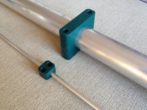
Insulated elements
This is specified at the time of the design, it is interesting to see the design with and without insulated elements. Insulating the elements from the boom has the effect of shortening them slightly, but why not have a play with the calculator and see the difference. The insulators I used were 4mm ABS plastic, cut into strips but you can use anything to hand.
Driven element
Often the most difficult parts to complete, as it requires a split and insulation from the boom.
Options.
1/ Place a small plastic tube inside both parts of the driven element, thus making them rigid and then mounting this to the plastic insulator on the boom.
2/ Fix the driven element directly to the plastic insulator using 2 plastic clamps on each section. This should provide enough support to stop the element sagging or twisting.
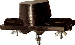
3/ Commercial VHF style dipole center.
Parts list / Supplier options.
Aluminum warehouse can supply lengths of aluminum in both imperial and metric sizes.
Black Plastic Nylon P Clips Mounting Cables Tubes Pipe Brake Motorcycle Car. These can be used to fix the elements to the insulator, they are available in various sizes. The clips allow the elements to be removed by simply pushing/pulling the element into the clip, and are therefore ideal for portable use.
Something more robust would be needed for a permanent solution.

Stauff clamps can be sourced online. These are more expensive than other options, but ideal for a permanent antenna build.
VHF dipole center available from your local rally, eBay, or online
Element insulator, search using 4mm ABS plastic sheet.
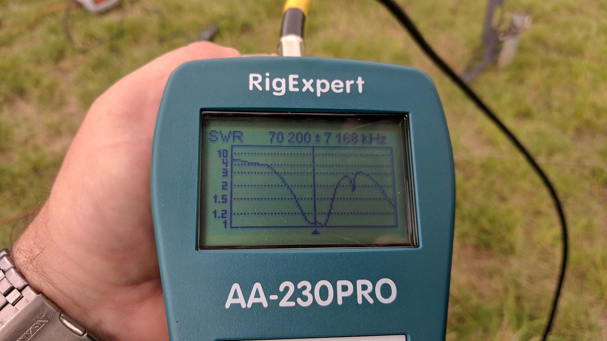
Closing thoughts
The antenna is a little quirky, the dip shows a good match at 70.200 and the bandwidth is wide enough to cover the entire 70 MHz band. The dip shown on the RigExpert is a little nonconventional, but it certainly has gain and good F/B ratio from the testing on-site.
Alternative designs by DK7ZB
Audio clips from testing.
GM4NFC Alex 520 KM
GI4SNA David @530 KM
July 2017 70 MHz Trophy Cup.
Very nice Dave. 4m looks like a fun band to experiment on. I wish that we had that spectrum allocation here in Canada.
73 de Mike VE3MIC
Thanks, yes it’s a little strange at times and we are lucky to have the band. Makes it much easier that Icom support this band on some of their radios, and my HF linear also does 4m.
Hi Dave, Do the dimensions allow for shortening in order to meet the 70.2MHz?
73
Chris M0LXG
Hello Chris, the antenna already meets its design 70.2 based on the dimensions included. What Freq would you like to use? An alternative design is by DK7ZM have a Google and maybe look at his designs also. 73 Dave
Thanks Dave, I will build mine to the same dimensions for the same frequency.
Hi Dave, Just wondering what is inside the black box?
Its a matching section, the antenna is not 50 Ohm so requires some coax to match to 50 Ohm