Welcome to Part 1, this covers the initial build of the U3S, Part 2 covers the addition of the LPF relay board.
Some month ago I purchased a Ultimate 3S QRP transmitter from QRP Labs. The latest version is the ultimate 3S and it comes with a number of options.
Over the christmas holidays I decided to make the project, inspired by Dave G7UVW and George M1GEO activity on QRSS over the holidays. I have used WSPR before from home, but really wanted a QRP transmitter that I could leave on over night, without running the main radio. The answer is one of these kits, as they are very low power consumption, and flexible enough to run multiple modes / bands.
The transmitter can be configured to run on any band between 2200m to 2m (136 KHz to 144 MHz) with a suitable low pass filter. I have linked a table showing actual TX frequencies online.
I had purchased the Ultimate 3S, Si5351A synthesiser module, Low Pass Filter for 14 MHz and the QLG1 GPS unit. Other kits / options are available, and the project is modular so you can pick and choose the options that work for you.
I found the instructions really easy to follow, and coupled with the pictures component identification was easy. I did use a magnifying glass to check some of the component values, and the “quality” of my solder joints. Starting with the GPS module, and then the synthesiser I found the build easy to complete. I then moved onto the main 3S transmitter, this again has various options, but I decided to get the basic version running with one transistor before considering other higher power options.

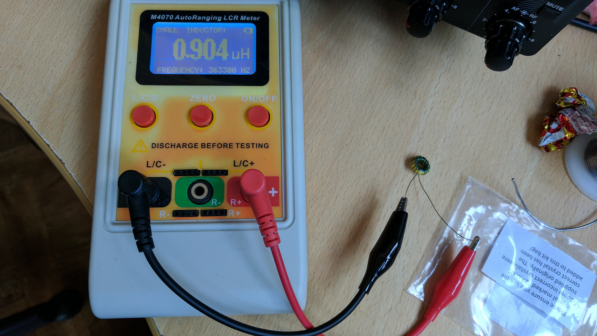
I found having an LC meter helped when winding the torriods, but the values didn’t seem to be too critical so this was more of a confidence check.
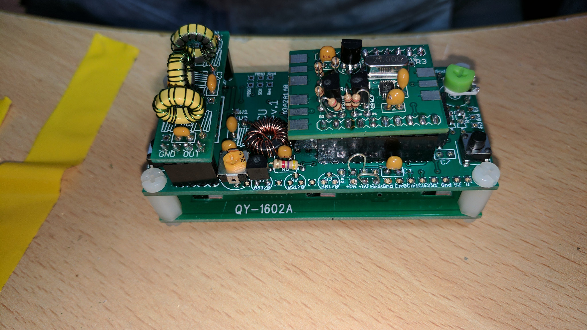
You can see the completed LPF on the left, very compact and the instructions suggest this is good for 10w.
Here you can see the completed main board, with synthesiser and LPF installed. You can see on the bottom of the board the single transistor installed, with space for more.
 The instructions suggest a stable 5v power supply is required for the single transistor version, and looking around the junk box I found an obsolete USB blackberry phone charger. This seemed ideal, so off came the USB plug, replaced with some wire and heat shrink. This also provided a current limited supply, with the USB charger rated at 1A being more than adequate for the TXM.
Once built, assembled and powered the kit goes into diagnostic mode (assuming no blue smoke). Mine powered up and worked without any further modifications, but any issues are likely to be mine as the kit is very well designed.
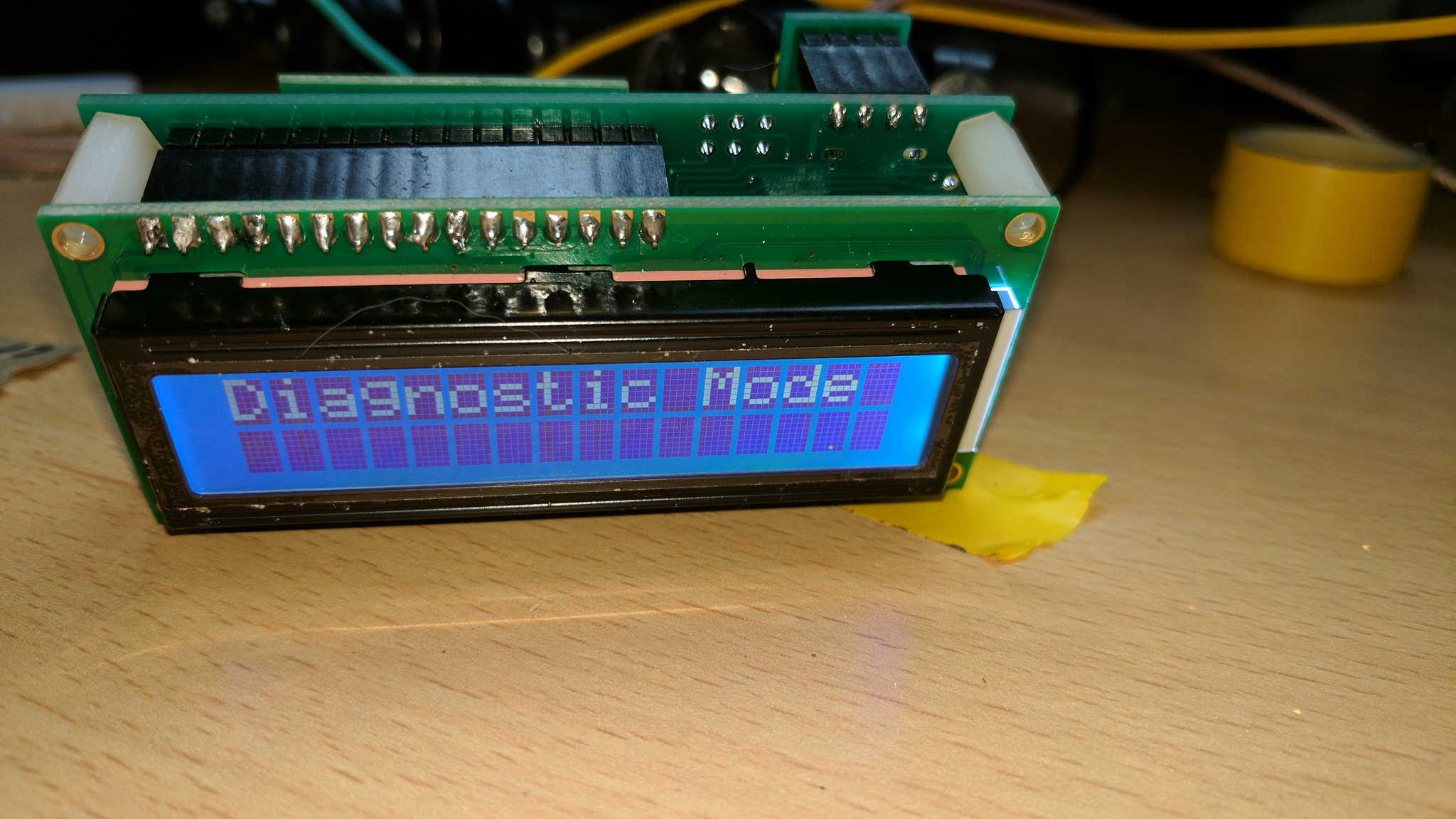
This provide the initial indication all is well, next you need to adjust the display contrast and the the PA bias.
The instructions suggest you should expect around 250mW on 10 MHz, with the power falling away as you move higher in frequency.
I found I could achieve 250mW with ease on 14 MHz as can be seem here on my QRP power meter.

The next stage was to get it on air, this took a little longer than expected, as getting a GPS fix indoors required some careful positioning of the patch antenna. I also found the menu system a little difficult to navigate, its not actually difficult but you have so many options its a little overwhelming to start.
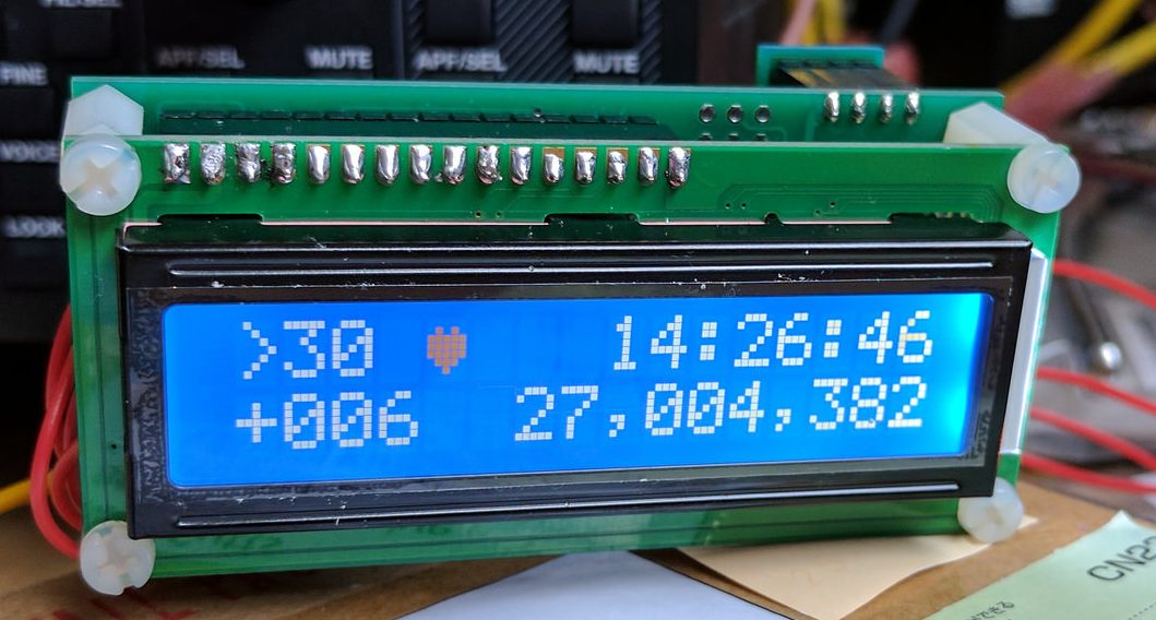
I think the priority should be getting the GPS feed configure, once this is correct the display shows a heart beat. The default option is this is not configured in the software, and so even connecting up the GPS unit will not start this process. The next is frequency correction. If you have the GPS unit fitted this can be completed automatically, but you still need to setup the calibration time, and frequency correction steps in the menu.
Calibration completed showing 27.004.382 (4.382 Hz correction) and the hart beat symbol for GPS lock.
 On my first attempt I had not set this up correctly, and while it was slowly correcting the frequency the number of iterations would have been extremely high before I had anything like an aligned txm.
I found the FAQ helpful, as this told you the specific steps to take and values to input. I set the operating frequency to 14.0971 and after a few calibration cycles it worked!
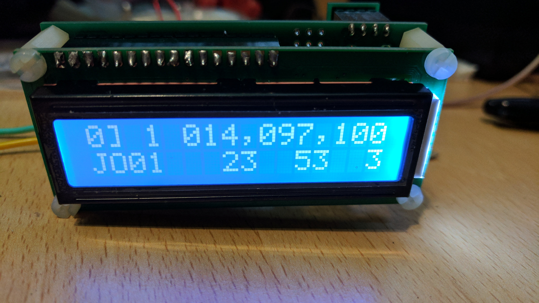
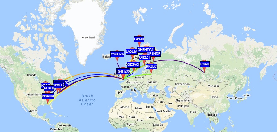
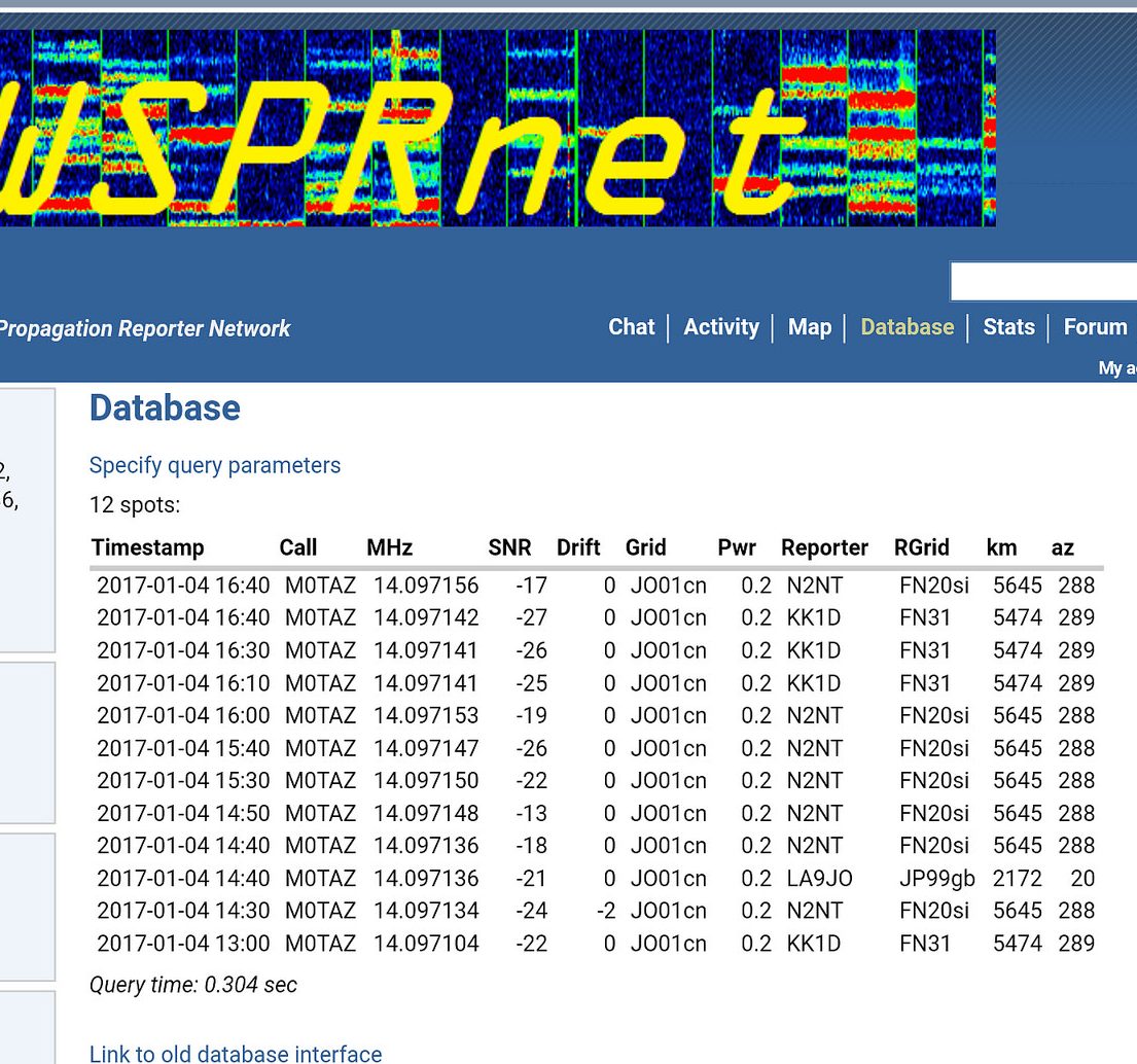
Here you can see the unit is transmitting WSPR from JO01. The first spot I received was from KK1D at 5474 KM, not bad for 250 mW.
Its always nice when you build something and it works 🙂
Other suggested frequencies

Update 17/1
The TXM has continued to work flawlessly without issue. Ive move the antenna over to a dedicated 1/4 ground mounted roach pole with 4 radials. The power has been checked again and its 250 mW, the best spot I have is from 6500 KM away into Asiatic Russia to the East, and West around the same distance into the USA.