
Welcome to Part 2, the project started in Part 1 and this covered the initial build and setup of the Ultimate 3S. Changes to the TXM are possible but require you to manually change the LPF and input a new frequency via the software.
QRP labs have developed a relay switched LPF kit, and Part 2 covers the assembly and operating of this unit.
Building this kit twill allows you to increase the bands from 1 to 6. The relay kit has space for 5 further LPF, and you can continue to use the 1 from the original kit giving you a total of 6 band operation.
LPF are available for all bands from 136 Khz to 50 MHz.
I chose to order and make up the following 3.5 MHz, 5 MHz, 7 MHz, 10 MHz and 21 MHz. The process of assembling the LPF is very easy, the circuit is standard and simply requires different values of capacitor or inductor to achieve the correct roll off characteristics. The Low Pass Filter kit is based on the G-QRP technical notes, a design by Ed Wetherhold W3NQN. Ed has published an interesting article on band pass filters published in QST dated 1998.
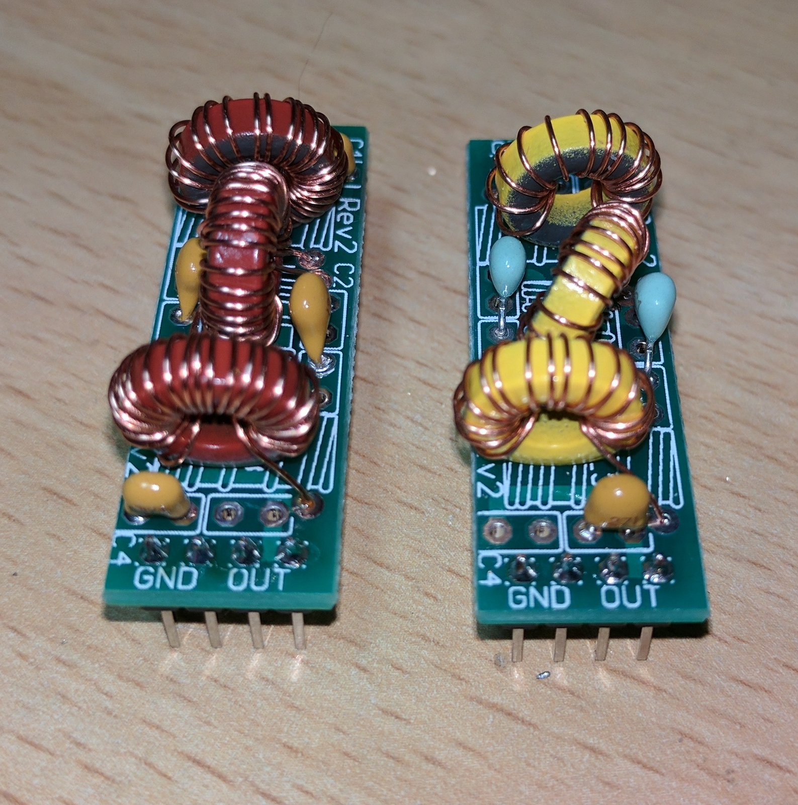 Winding the toroids without doubt takes the longest, and with 15 to wind I spaced it out over the course of the day. Here you can see the 5 MHz and 10 MHz (left) LPF assembled and ready for installation.
The winding of the toroids for the LPF was interspaced with adding the relays to the band switching relay kit.
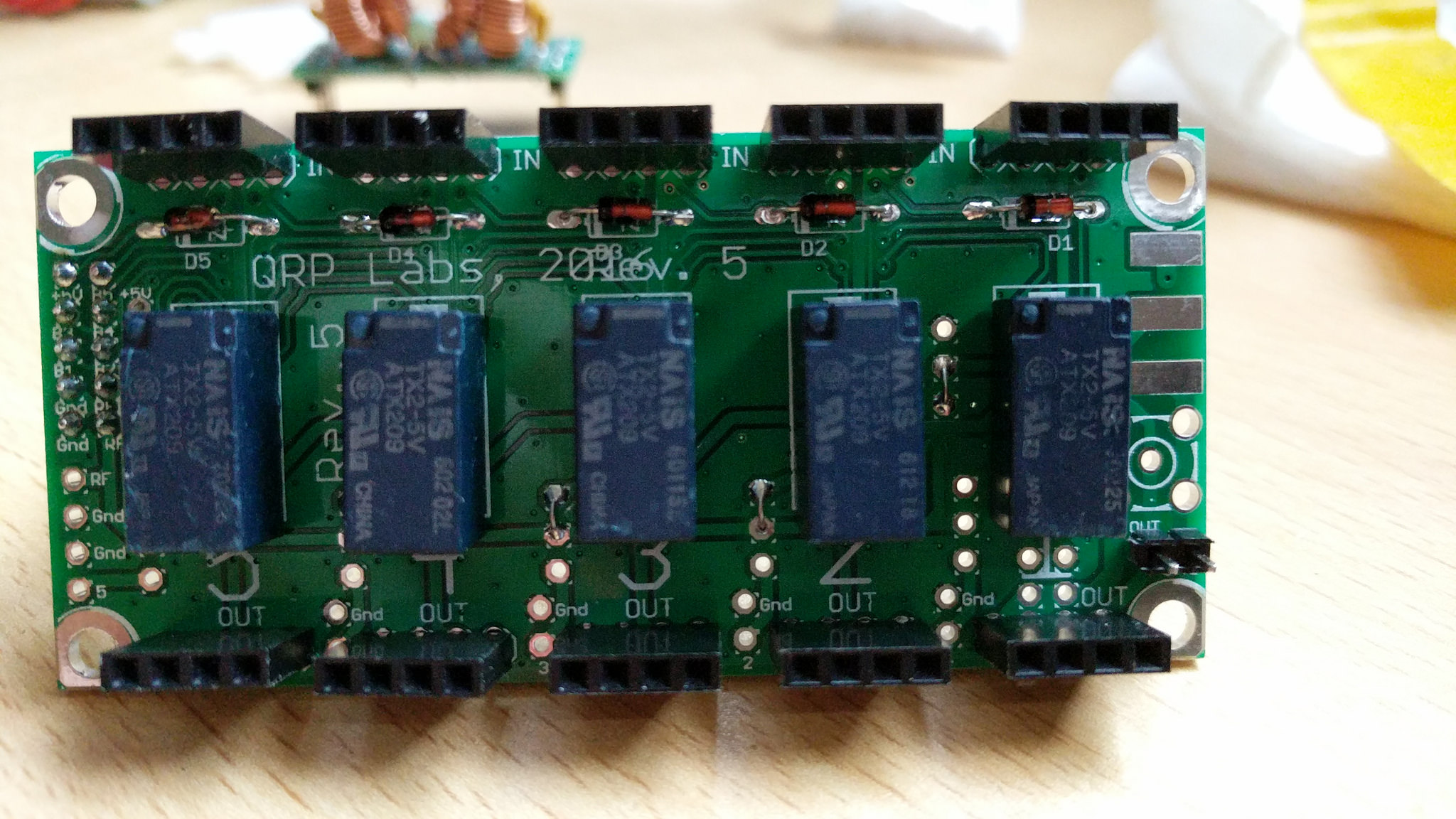
The kit uses Panasonic TX2-5V relays, the kit includes 6. One is to mount on the Ultimate 3S main board.
Here you can see the kit is completed, and awaits LPF. Its important to note the highest frequency LPF must be fitted in position 1. The positions are numbered 1 to 5, with position zero being on the main Ultimate 3S board.
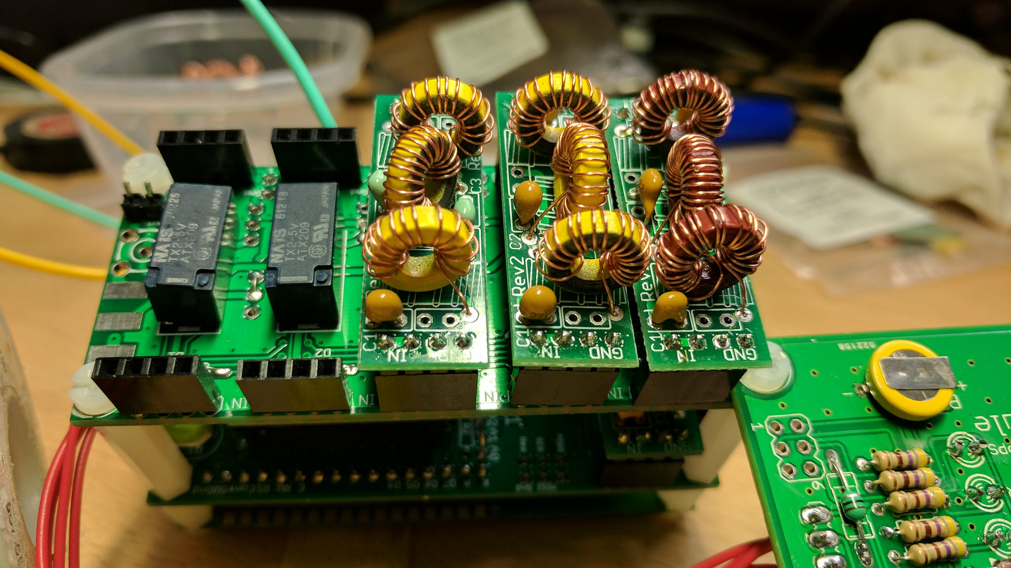 The next stage is to mount the relay LPF on top of the main Ultimate 3S, the system has been designed to stack on top of each other, providing a very neat solution. In this example I have 3 LPF fitted, with room for a further 2. Its seems logical that you should arrange the LPF in band sequence, I don’t think this is strictly necessary but it helps the planning and programming later.

The completed item is installed, working from right to left 21, 10, 7, 5 and 3.5 Mhz. I also installed a SMA socket onto the relay board, as the RF is now routed from here after the expansion. RF can be coupled in one of 3 ways, the board has options for SMA upright, SMA side mount and pin connections. The SMA upright doesn’t provide enough clearance with the LPF directly above it, so you could try a right angled SMA socket. I didnt have one so opted for the SMA mounted on its side.
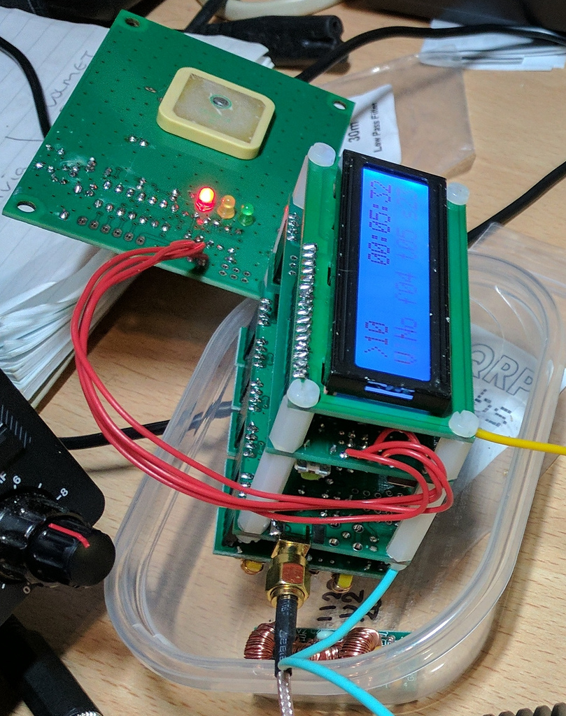 The RF is now routed to the side angled SMA, here you can see the modular design with the GPS module to the top.
QRP labs to stock cases for the completed project, and I have recently ordered one to provide the finishing touch.
Further thoughts and lessons learned.
I need to investigate why the o/p power has dropped on 14 MHz, as a single band unit I was getting 250 mW, but this has recently dropped to 100mW. I suspect this may have something to do with the LPF arrangement, as all RF must now pass via the LPF placed in position 1. This shouldn’t present an issue as LPF 1 should pass anything below 21 MHz, but without a spectrum analyser or a Vector Network Analyser I haven’t been able to investigate further at this stage. Other bands have an o/p between 200 and 300 mW.
Its worth mentioning again you need to take out the original U3S board and add a relay and diode before LPF zero. This isn’t required unless you have added the LPF relay kit.
You will need to cut jumpers previously installed on the U3S, you need to cut W0 – W1 and W2 – W3.
Configuration in the menu system for multi band operation is a little fiddly, but once you understand the steps needed its easy enough to follow.
You will need to change the menu option TxS to increase the amount of transmit slots from the default 3 to 6 in order to make use of the enhanced LPF.
Typical display options explained. starting from top left
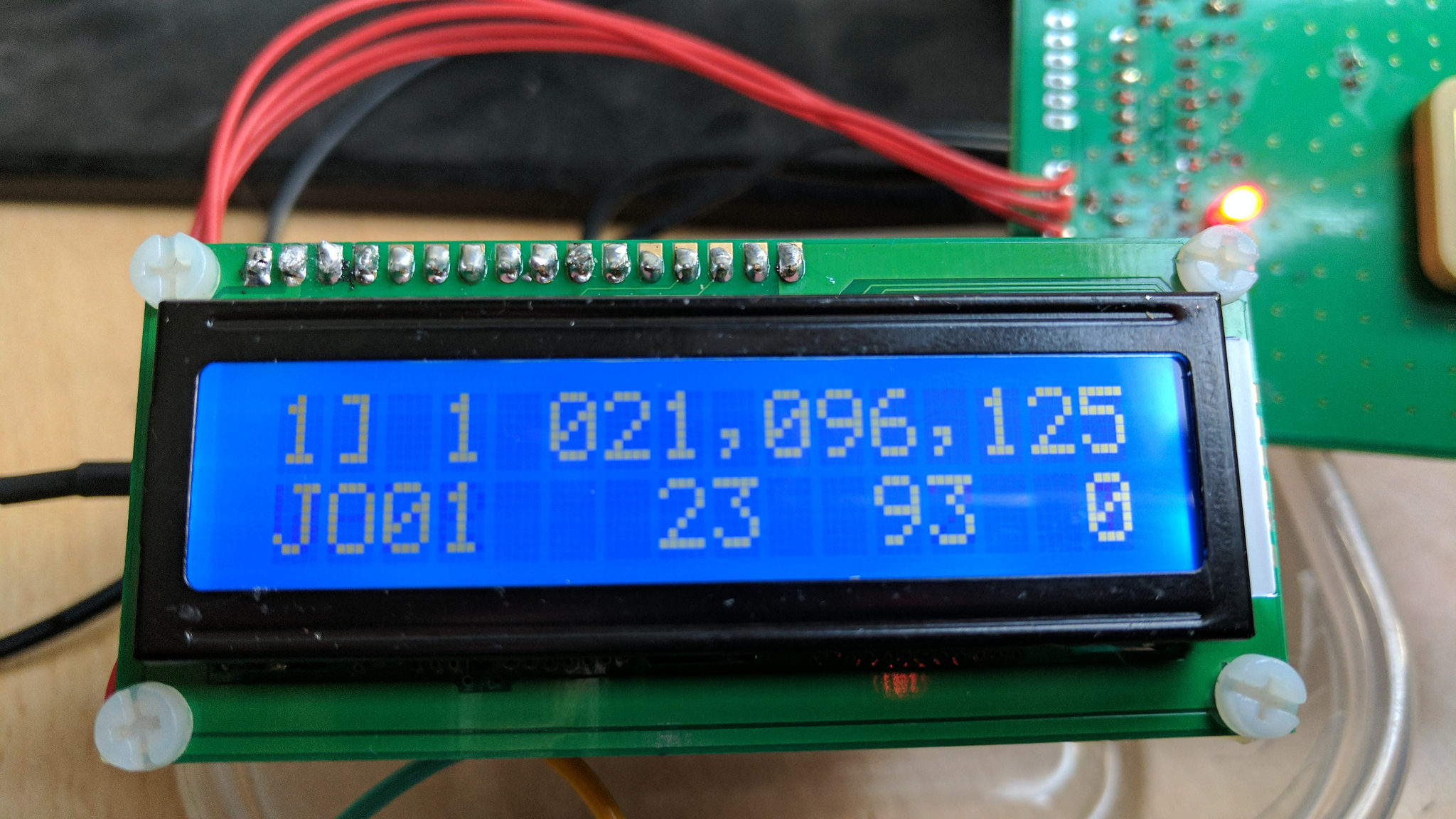
1] is the sequence number, this indicates its the second mode option (zero then one)
1 This indicates it will select LPF 1 (check this corresponds to the correct frequency LPF) For example number 5 here would select the LPF in slot 5
021,096,125 is the frequency for TXM. You can find a complete list of freq in part 1 of the ultimate 3S construction.
JO01 is my locator, shown when in txm
23 is my power in dBm
93 is the symbol number (WSPR is 162 for a complete message)
0 is the tone currently being sent.
If you want to add additional tx sequences, then this can be done by editing the menu system, just ensure you have the correct frequency and LPF slot set.
This is covered in great detail in the firmware manual.